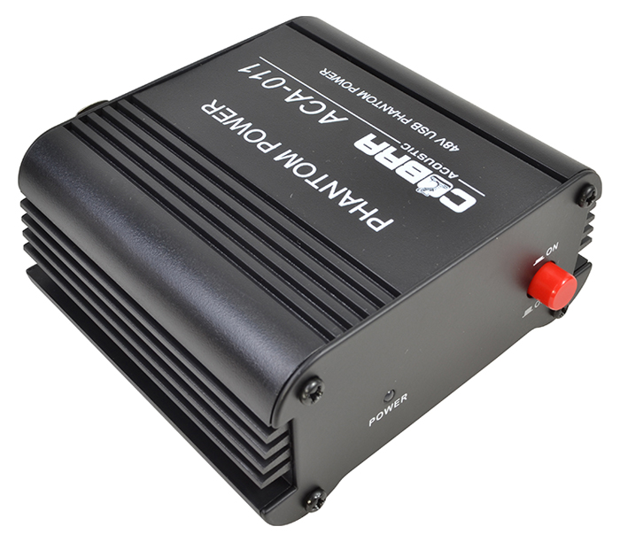

- CONNECT 48V PHANTOM I POWER SUPPLY TO IBOOSTER DRIVER
- CONNECT 48V PHANTOM I POWER SUPPLY TO IBOOSTER DOWNLOAD

To read other interesting DIY projects: click here This article was first published on 13 August 2019 and was updated on 4 March 2021.Phantom power is the mode of supplying DC voltage through a balanced audio connector to power a condenser microphone. Now he is working as an electronics engineer in the private sector in Bulgaria. Petre Tzv Petrov was a researcher and assistant professor in Technical University of Sofia (Bulgaria) and expert-lecturer in OFPPT(Casablance), Kingdom of Morocco.
CONNECT 48V PHANTOM I POWER SUPPLY TO IBOOSTER DOWNLOAD
3: Components layout for the PCB Download PCB and component layout PDFs: click here Connect LED1 and LED2 on the front panel to indicate power status. After assembling the circuit on the PCB, connect the 5V regulated power supply across CON1. The circuit does not need any adjustment.Ī PCB layout of the DC-to-DC converter is shown in Fig. We can use both the outputs, OUTPUT1 and OUTPUT2, at the same time under the condition that total current is below 60mA. L2 (usually from 22µH to 220µH for current above 100mA) and C6 produce additional filtration of the voltage produced by the DC-to-DC converter. So, second output (OUTPUT2) is provided after LC filter. Ripples at OUTPUT1 are around 50mV at 50mA load, which may be too high for some applications. Schottky or ultrafast diode can either be SB1A0, SR1100, SS110 or SR180.Ĭ4 and C5 are the first filtering capacitors. Schottky diode D2 should preferably be rated at least 100V. Voltage on pin 5 of IC1 should be equal to internal reference voltage or around 1.25V (1.21V to 1.29V). Output current is up to around 50mA, which is enough for several applications including microphone amplifiers. It can be calculated using the approximate relationship: Output voltage is around 48V and can be adjusted with R4. Inductor L1 is in the range of 100µH to 150µH for current above 1.8A. Operating frequency of MC34063A is in the range of 40kHz to 60kHz, and depends mainly on capacitor C3.
CONNECT 48V PHANTOM I POWER SUPPLY TO IBOOSTER DRIVER
Resistor R3 limits the current for the inbuilt driver transistor of IC1. Resistor R2 limits the maximum switching current to around 1.5A, as per relationship: Diode D1 protects the circuit from reverse input voltage. Fuse F1 protects the circuit from any continuous over-current input.

Input power supply ranging from 5V to 7V can be applied to connector CON1. 1: Circuit diagram of 5V DC to 48V DC converter It is built around boost/buck/inverting switching regulator MC34063A (IC1), two rectifier diodes 1N4007 (D1 and D3), Schottky diode SR1100 (D2), two 5mm LEDs (LED1 and LED2), two inductors (L1 and L2) and a few other components. The circuit diagram of the 5V DC to 48V DC converter is shown in Fig. This circuit presents a solution for converting 5V DC to 48V DC using a popular MC34063A IC. 5V DC power supplies are easily available at low cost. There are many application circuits that require 24V and 48V phantom power supplies, but these DC power supplies are costly and not easily available. This circuit presents a simple and low-cost DC-to-DC converter for phantom power supplies used in mixing consoles, microphone preamplifiers, telephone systems and similar equipment.


 0 kommentar(er)
